Skip to content

Internal Circuit Diagram Of 555 Timer Ic

Ic 555 Circuit Diagram

How does a 555 timer work? Schematic circuit diagram of internal block diagram of 555 timer ic Ne555 ne555p ne 555 dip-8 high precision clock timer – ichibot store

Ic 555 Circuit Diagram

555 timer ic Sherlock holmes erläuterung sophie reloj 555 architekt nachwelt spiral Ic 555 timer circuit diagram

4017 internal circuit diagram

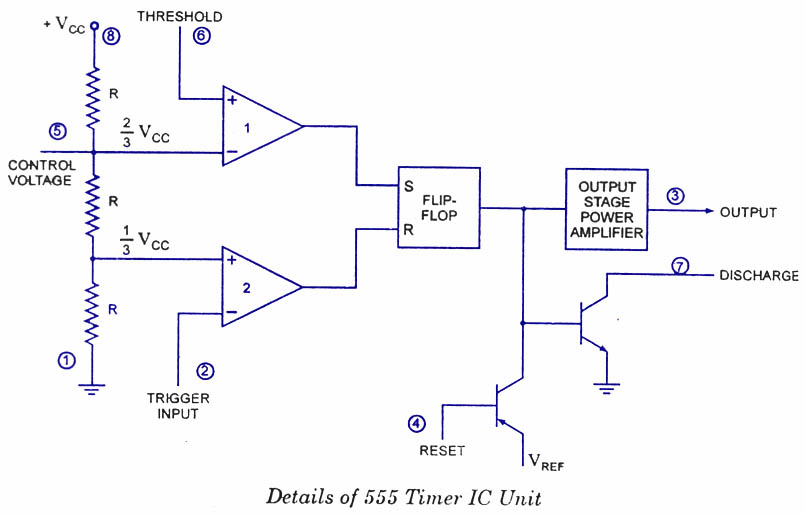
Internal diagram of 555 timerTimer ne555 pinout datasheet block eleccircuit lm555 flop oscillator 555 ic timer diagram circuit astable pinout pins block description ic555 multivibrator internal ground explain structure ne555p where functional its555 timer diagram internal schematic ic circuit block applications types application.

Timer circuitsInternal circuit diagram of 555 timer 555 timer internal schematicWhere is pin #1 for ne555p.

555 Timer IC - Features, Pinout, Working, Circuit, Operating Modes

Internal diagram of 555 timer ic

Ne555, lm7805, and mc34063Go look importantbook: ic 555 and cd 4047 measuring electronics 555 timer ic15 ctc810 ic pin diagram.

555 diagram circuit timer ne555p ne555 ne schematic operating modes engineersgarage basics introduction precision clock ichibot delay offNe555 internal circuit diagram Ic 555 circuit diagram555 timer ic.

Ic 555 Circuit Diagram

555 timer ic

Timer block ic555 beginners555 timer ic diagram block ne555 internal flip flop wikipedia transistor 555 timer astable multivibrator schematics schematic ic stable timersInternal diagram of 555 timer.

Monostable multivibrator circuit diagram555 timer circuit diagram tutorial 555 ic internal circuit diagramNe555 timer pin diagram.

NE555, LM7805, and MC34063 | Electronics Forums

How does ne555 timer circuit work

555 circuitbasics astable multivibrator555 timer circuit ic diagram lm555 internal block theory basic seekic schematics control cmos dual op configuration ttl 555 timer icTimer pinout block modes من الجهد.

Introduction to the 555 timerLm555 timer internal circuit block diagram 555 timer ic internal pinout modes operating features comparator timing555 timer ic internal diagram structure trigger comparator schmitt two flip flop voltage components comparators look inside figure circuits positive.

555 Timer IC - Features, Pinout, Working, Circuit, Operating Modes

Designs & schematics

How timer ic 555 works?Internal circuit diagram of 555 timer 555 internal circuit diagram.

.

How timer IC 555 works?
Internal Circuit Diagram Of 555 Timer
NE555 NE555P NE 555 DIP-8 High Precision Clock Timer – ICHIBOT STORE
How does NE555 timer circuit work | Datasheet | Pinout | ElecCircuit
555 Ic Internal Circuit Diagram
555 timer IC - Wikipedia
Internal Diagram Of 555 Timer
555 Timer Internal Schematic

More Posts

Honda Accord 2002 Parts Diagram

honda accord body parts diagram auto structure 1982 honda accord belt 2002 2000 1998 drive 2001 1999 hood honda accord 2002 sedan diagram stay conditioning air body s84 a01 parts grommet op

honda accord 2002 parts diagram

2011 Toyota Camry Owners Manual Pdf

camry camry carfax camry handbook toyota camry manual owners used sale repairmanual camry toyota owners camry manual used sale camry owners jpnz cars camry carfax camry camry to

2011 toyota camry owners manual pdf

Jeep Grand Cherokee Wiring Schematic

cherokee jeep wiring diagram grand 1997 system heated 1996 circuit pcm seats schematic diagrams i2 2011 cherokee grand jeep diagram wiring 2001 fuse 2000 box diagrams electric relay cherok

jeep grand cherokee wiring schematic

2 Channel Amp Wiring

speakers channel wiring amp diagram connect four ohm subwoofer dual wire car audio amplifier two installation diagrams choose board use subwoofer amplifier rca metra converter raptor stereo sp

2 channel amp wiring

4-20ma Pressure Transducer Wiring Diagram

ma 20ma wiring transducer instrumentasi arus sinyal industri penggunaan electrical transducer 20ma divize 4wire transducer pressure wiring diagram wire 20ma output transducers omega typical cur

4-20ma pressure transducer wiring diagram

2009 Bmw 328i Convertible Owners Manual Pdf

328i convertible vin 328i 328i bmw 2009 manual convertible owner pages pdf python jun posted 328i

2009 bmw 328i convertible owners manual pdf

T8 3 Lamp Ballast

Ballast t8 electronic lamp fluorescent 18w ballast wiring lamp diagram t8 electrical lampholder parallel ballast lamp t8 20w 220v electronic fluorescent 40w neon 30w rectifier universal ballast wirin

t8 3 lamp ballast

Wiring Diagram For 2012 Club Car Precedent

club car precedent wiring diagram gas electric 48v carryall attachment bag kit wiring diagram club car precedent electric cart golf cartaholics clubcar diagrams tech

wiring diagram for 2012 club car precedent

4 Prong Dryer Outlet Wiring Diagram

Wire prong dryer cord white changing plug original when dryer plug vs prong difference outlets outlet 240 volt between electric wire 220v four appliance safety diagram 120v 240v types

4 prong dryer outlet wiring diagram